- Home
- Symmetry Blog
- Tech 101 From Symmetry Electronics: I2C vs SPI
Tech 101 From Symmetry Electronics: I2C vs SPI

About Anuja Upale
SPI: Serial Peripheral Protocol
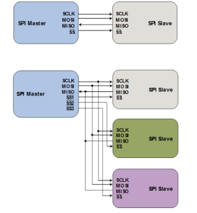
SPI uses a Master-Slave configuration. Master will decide which slave to contact. This protocol supports only one master.
SPI protocol uses 4 wires to connect two devices. The four signal lines used are: Clock signal (SCLK), Slave signal to indicate which slave (SS), MOSI (Master Out- Slave In) which sends data from master to slave and MISO(Master In-Slave Out) which sends data from Slave to the Master.
Working: For example, in SPI protocol master wants to send data to a slave. Master will indicate which slave by pulling the respective SS line low. Then master will set SCLK for a frequency both master and slave are familiar with. Master will then use MOSI line to send the data. If Master wants to receive the data it will do so on the MISO line.
SPI protocol does not incorporate any control bits or ACK for the data sent. It also does not specify any max speeds for communication or flow control.
I2C: Inter-Integrated Circuit
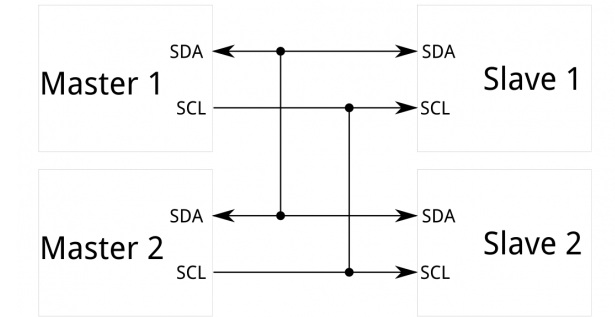
I2C also uses Master-Slave configuration to communicate between devices. Although I2C can support multiple masters and multiple slaves.
I2C uses only 2 wires for communication. One is clock which is called Serial Clock (SCL) and the other one is ‘Serial Data’ (SDA). Any number of masters and slave devices can use these 2 lines to communicate with each other.
Since there is no line that indicates which master or which slave, there needs to be an addressing scheme which will indicate the device being communicated to. Each device will have a 7-bit unique address. I2C also supports control bits for start, end and ACK of the data.
Working: We will consider the same example. A master wants to send data to a slave. First master will have to send START signal to indicate that it is starting communication. This signal will alert all the devices sharing the I2C bus. Then master will send the 7-bit unique address of the device with which it wants to communicate. Along with the address it will also send the type of the operation either Read or Write. The slaves will match the address to see if request was intended for them or not. If the address matches, slave will send ACK to the master. Once master receives this ACK then it will send the data. Once all the data is sent it will signal STOP.
In case master has to receive data, then it will indicate that to the slave and slave will send the data.
There are 3 different modes for I2C depending on the speed: 100 kbps, 400 kbps and 3.4 Mbps.
I2C vs SPI:
Similarities:
- Both protocols are primarily used for communication with peripherals.
- Both employ Master-Slave configuration for communication.
- The working for both protocol is essentially similar. Clock is generated by the master. Data is written or read on the edges on clock.
Differences:
- Resources required:
SPI requires at least three lines (MISO and MOSI can be combined) whereas I2C requires only 2 lines. Additionally, in SPI Master will require one SS line per slave connected.
- Throughput:
SPI offers much higher data rate than I2C.
- Advanced features on I2C:
I2C offers advanced features such as ACK, addressing scheme for devices & multi-master configurations.
- Simplicity:
SPI is very simple and easy to implement.
References:
- https://learn.sparkfun.com/tutorials/i2c
- http://www.byteparadigm.com/applications/introduction-to-i2c-and-spi-protocols/
See other Tech 101 posts from Symmetry Electronics:
Tech 101 From Symmetry Electronics: What's a PCB?
Tech 101 From Symmetry Electronics: Hall Effect Sensors
Tech 101 from Symmetry Electronics: What Is Z-Wave?
Tech 101 from Symmetry Electronics: What is Thread?
Tech 101 from Symmetry Electronics: What is Zigbee?
Tech 101 from Symmetry Electronics: What is LoRa?
Tech 101 from Symmetry Electronics: What is GNSS?