- Home
- Symmetry Blog
- External Antennas: Different Types and Advantages | Symmetry Blog
External Antennas: Different Types and Advantages | Symmetry Blog

About Augustine Nguyen

Antennas are major components used in wireless technologies that range from small antennas embedded in mobile devices to massive antenna arrays found in cellular or satellite base stations. Although antennas exist in many shapes and sizes, virtually all of them belong to one of two main categories: Internal or External. Internal antennas are embedded within a device’s enclosure and are relatively out of reach to the end user. These range from small chip or PCB-etched antennas integrated onto the board, to flexible printed circuit (FPC) antennas that are mounted to the inside of a product’s enclosure. Alternatively, external antennas are mounted on the outside of a device’s enclosure via an RF connector. A typical example would be a “rubber-duck” antenna that mounts to the outside of an internet router. The purpose of this article is to outline the different types of external antennas, their key performance parameters, and their specific design advantages.
Not sure which type of antenna is optimal for your design? Reference our FREE comprehensive Antenna Selector Guide.
Important External Antenna Performance Parameters
Bandwidth: This is defined as the optimal range of frequencies for an antenna to efficiently transmit and receive signals. For example, a Bluetooth antenna performs best in the 100 MHz bandwidth of frequencies at 2.4 - 2.5 GHz. By the inherent nature of antennas, this hypothetical Bluetooth antenna would also be susceptible to frequencies outside it’s intended bandwidth, but it is over this specific range of frequencies (2.4-2.5GHz) that the antenna is expected to perform optimally at a certain efficiency (%) level. However, this is dictated by how precise the antenna element is designed. An antenna’s bandwidth is typically defined in terms of Voltage Standing Wave Ratio (VSWR)–a parameter that measures the amount of power that is reflected back to a radio from an antenna (Figure 1). The less power reflected back to the radio, the more efficiently the antenna is able to perform. The preferred VSWR for a particular bandwidth is usually less than or equal to 3:1. For example, an antenna that claims to operate from 100 to 400 MHz may state that its VSWR is less than 1.5 within this bandwidth efficiency. In this case, it would imply that the antenna is expected to reflect around 4% of the power back to the radio.
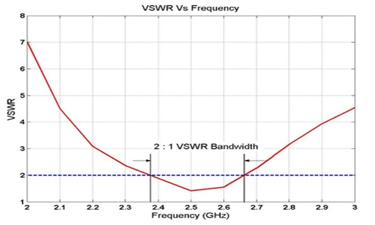
Figure 1: Antenna bandwidth defined by VSWR.
Radiation Pattern: This is less of a numerical parameter and more of a graphical 3D representation of the energy distribution surrounding an antenna. While a 3D radiation diagram is a full representation of an antenna’s energy distribution, a 2D diagram is also beneficial in providing an easier way to identify where most of the antenna’s energy is concentrated. The main purpose of a radiation pattern is to visualize how omnidirectional (Figure 2) or directional (Figure 3) an antenna is. An omnidirectional antenna is described as having a radiation pattern that is relatively the same in all directions within a single plane (i.e. horizontal x-y plane). Conversely, a directional antenna has less of a symmetrical radiation pattern, with most of its radiated energy concentrated in a single direction.
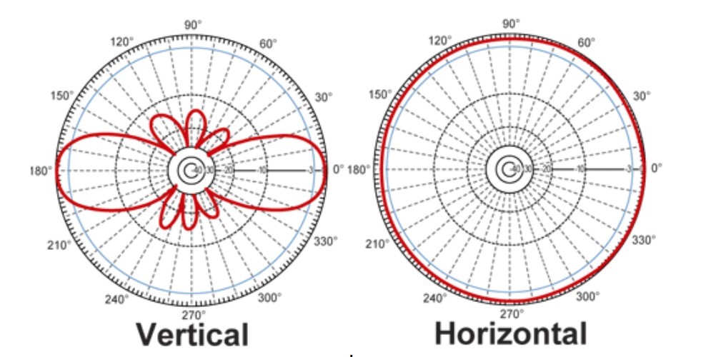
Figure 2: Generic vertical and horizontal radiation pattern of an omnidirectional antenna.
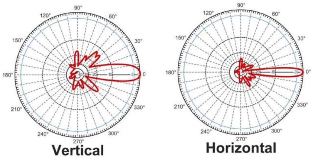
Figure 3: Generic vertical and horizontal radiation pattern of a directional antenna.
Gain: This is the first parameter that is considered when evaluating an antenna’s performance. The gain is always described in context of the antenna’s radiation pattern, as it is defined as the signal strength in the direction of its peak radiation when compared to that of an isotropic source. An isotropic source is meant to serve as a “reference antenna,” although it does not exist physically. The “reference antenna” serves as an excellent comparison source to that of an actual antenna, as the radiation pattern is consistent in all directions. Reference (Figure 4) for the general formula for antenna gain (dBi).

Figure 4: Gain (dBi) formula.
For any antenna in practice, increasing its gain means you are increasing its “directivity”, which in turn increases the power in a desired direction at the expense of the power being radiated in other directions
External vs. Internal Antennas
Besides the obvious differences in size and form factor, external antennas offer a series of advantages for customer design in comparison to internal antennas–one being ease of integration. External antennas are typically designed to be “plug-and-play” solutions that simply mate to a transmitter via a specific connector. Conversely, internal antennas (like surface mounted chips) require additional design effort, as further antenna tuning and optimization is required. An internal antenna’s performance is influenced by the PCB ground plane, as it serves as an extension of the antenna. In this case, the board area and components on the PCB would have to be considered. Additionally, an impedance matching network may have to be implemented before the antenna feed point to account for these factors on the PCB that will detune the antenna. An internal antenna is also susceptible to signal loss caused by the product enclosure. On the other hand, the majority of external antennas are “ground plane independent,” making them an ideal approach for customers seeking a solution that requires fewer design resources and shorter time to integrate to allow for a more rapid time-to-market.
In addition to ease of integration, external antennas offer performance advantages in comparison to internal antennas. Overall, external antennas offer superior range and sensitivity due to the nature of their larger size. This often results in a higher rated gain (dBi) than their internal counterparts. Provided their higher gain, external antennas offer greater directional behavior for applications where signal transmissions are required to be concentrated in a specific direction. Another important factor to consider is that a larger antenna is required to support lower frequencies with longer wavelengths. Because of this, many high gain external antennas maintain a bandwidth that spans in the lower sub-GHz range with acceptable performance.
Due to its smaller size, an internal antenna would not function as well to support lower frequencies. For example, it would be difficult to find an internal antenna that could compete with an external antenna in terms of performance in the 400MHz bandwidth. All these inherent performance advantages (superior range, sensitivity, and ease of integration), combined with the fact that external antennas are outside the enclosure thus providing them with a better signal line-of-sight, makes them more suitable for applications with demanding requirements. However, customers must consider cost when pursuing this option, as additional manufacturing processes and materials are required to produce larger external antennas compared to something like a simple ceramic chip antenna.
Types of External Antennas
Omnidirectional Antennas - Terminal-mount, Whip, “Rubber Duck,” Outdoor Dipole
These types of antennas are akin to what you would find on wireless access points. A typical construction would consist of the antenna element enclosed within a rubber or plastic sheath with an exposed RF connector. These omnidirectional antennas are always ground plane independent, making simple coupling to the transmitter the only requirement for integration. Due to the non-directional nature of these antennas, they are meant to be vertically oriented to the ground, as they tend to radiate extensively in its horizontal (x-y) plane. Any wireless applications that require Point-to-Multipoint communication would benefit most from this type of radiation pattern. For example, any office environment where a router is needed to transmit and receive signals from many client devices like computers, phones, or any end-node modules.
Examples of Omnidirectional Antennas available at Symmetry Electronics:
- Taoglas Antennas:TG.55.8113, TG.45.8113
- Abracon Antennas:AEACAC198013-S698, APAMPSLJ-140
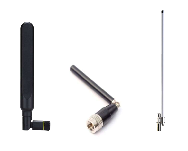
Figure 5: Examples of Terminal-mount, Whip, “Rubber Duck,” Outdoor Dipole Antennas.
Omnidirectional Antennas - Puck Style, Magnetic-Mount, Screw-mount
These “puck-style” antennas are meant to be mounted flat upon a surface such as a ceiling or roof of an automobile. They can be mounted on a metal or non-metal surface depending on the antenna model. The form factor is a big distinguishable trait, as they are generally a more low-profile design, making them ideal for customers looking for a different aesthetic to a larger profile like a terminal-mount antenna. By design, many puck style antennas are also capable of supporting integrated Low Noise Amplifiers (LNA) to dramatically improve signal reception–particularly for weak incoming GNSS signals. Unlike whip style antennas, puck style antennas are often meant to be horizontally oriented to the ground or sky, as they tend to have more of a 360-degree coverage in the vertical plane. An example would be a Wi-Fi ceiling mounted antenna in the center of a single floor of an office. Signal coverage would have to be downward-facing to ensure proper reception to all the computers, phones, and printers below.
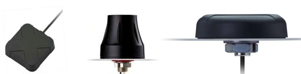
Figure 6: Examples of Magnetic-Mount, Screw-Mount Puck antennas.
Another advantage of the puck-style antenna form factor is that many different models can support multiple wireless protocols. This is optimal for any base station that wants to consolidate all of the different antennas needed for GNSS, Cellular, and Wi-Fi into a single form factor. A combinational antenna (Figure 7) like this is essentially three different antenna elements housed in a single enclosure, with each varying protocol having its own cable and connector.
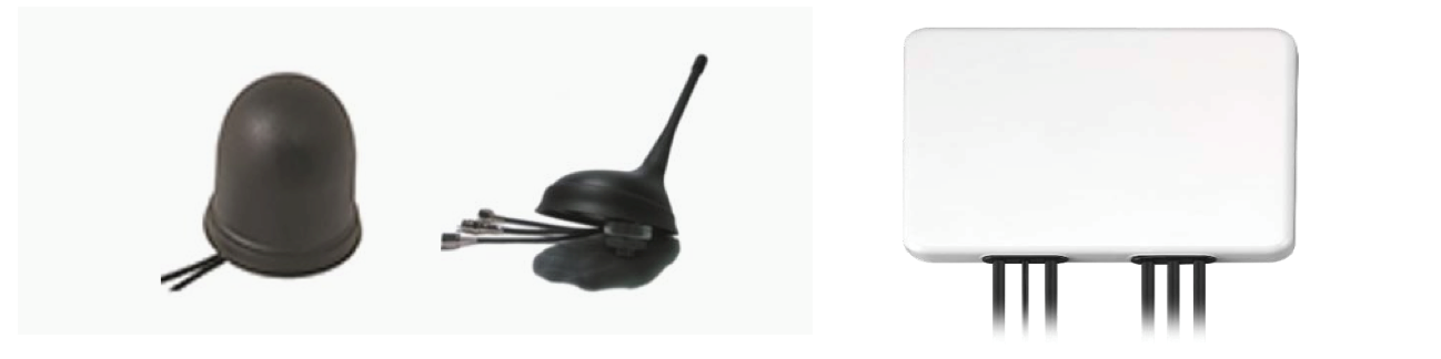
Figure 7: Examples of Combinational Antennas.
Examples of Omnidirectional Antennas available at Symmetry Electronics:
- Taoglas Antennas: TLS.01.1F21, G30.B.108111
- Abracon Antennas: AEACBK081014-M698, AEACAD097015-S698
Directional Antennas - Panel, Dish, Yagi Antennas
Directional antennas are focused on applications that depend upon long range Point-to-Point or Point-to-Multipoint communication. Because of the very focused radiation patterns of these antennas, you can always expect to see a high rated gain (dBi) in their datasheets (typically above 9dBi). Provided the high peak gain that these antennas provide in a singular direction, they are ideal for any demanding long-range application where an end-node device or a collection of devices are concentrated in a specific area. For example, a pair of office buildings that are sharing the same wireless network would have an outdoor-rated Yagi or panel antenna on each side with both antennas oriented towards one another to form a Point-to-Point communication link.
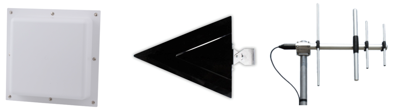
Figure 8: Examples of Panel, Yagi Directional Antennas.
Examples of Directional Antennas available at Symmetry Electronics:
- Taoglas Antennas: LPDA.05.032111
- EAD Antennas: LPM8270
Conclusion
The continuing evolution of IoT applications has resulted in an increase in demand for a wide variety of antenna options. Whether an engineer is leaning towards an internal solution to meet low cost, high volume, and size requirements; or towards an external solution for ease of design and guaranteed performance–the antenna will always be the crucial interface for your wireless system. It is recommended that the antenna be finalized early in a project’s design phase to ensure optimal performance. Fully settling on your product’s requirements (such as its PCB design, size, and enclosure) without taking the antenna into consideration will decrease your ability to modify your design in the event that a selected antenna does not fit or is incompatible. In addition to having a full understanding of your application’s requirements, being familiar with the different antenna types, their unique advantages, and performance parameters (gain, bandwidth, VSWR, radiation pattern) will always be instrumental in narrowing down the numerous antenna designs that exist today.
Need help narrowing down which type of antenna will work best for your specific use case? Consult our convenient Antenna Selector Guide for more information.