- Home
- Symmetry Blog
- Remote Keyless Entry Schemes for an Automobile Using the DecaWave DW1000
Remote Keyless Entry Schemes for an Automobile Using the DecaWave DW1000
Wednesday, August 27, 2014
The following are some general comments and notes on the implementation of keyless entry schemes, in particular, wireless schemes based on DecaWave’s Ultra Wideband technology.
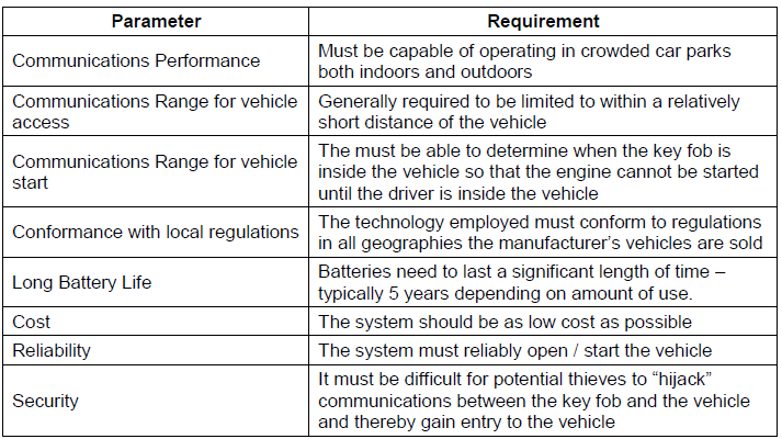
Requirements for a Keyless Entry System
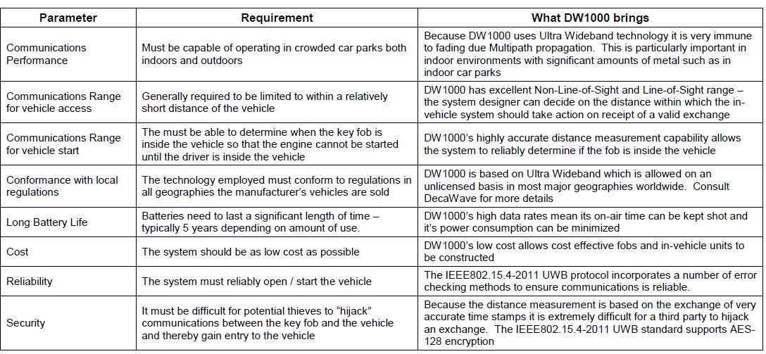
There are a number of fundamental requirements for a keyless entry system that can be summarized as follows:
Table: Requirements for a Keyless Entry System
Design Considerations
How to meet these requirements with the DW1000
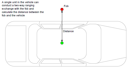
Problem: Measuring the distance from the vehicle to the car fob.
DecaWave Solution: Measuring the distance of the fob to the vehicle is not a problem. DecaWave’s technology allows distance to be measured to an accuracy of +/- 10cm (+/- 4in). A single transceiver in the vehicle can conduct a 2-way ranging exchange with the key fob when the appropriate key fob button is pressed and calculate the distance from the fob to the vehicle to an accuracy of +/- 10cm, as illustrated below.
Measuring the distance from the fob to the vehicle
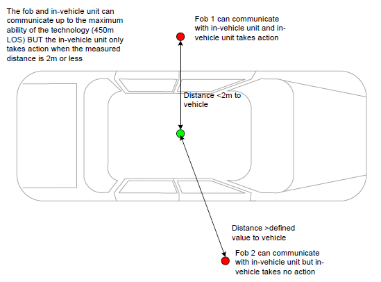
Problem: Required operation to be only within a given distance from the vehicle.
DecaWave Solution: DecaWave’s technology allows Line-of-Sight ranges of greater than 250m; however the in-vehicle unit can be configured to take action only when the measured distance is less than a certain vehicle manufacturer-defined value.
Operation only within 2m of the vehicle by allowing communications
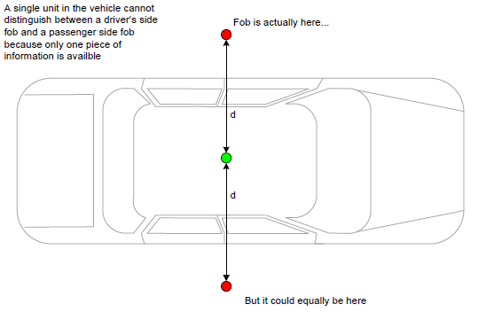
Problem: Detecting on which side of the vehicle the fob is located.
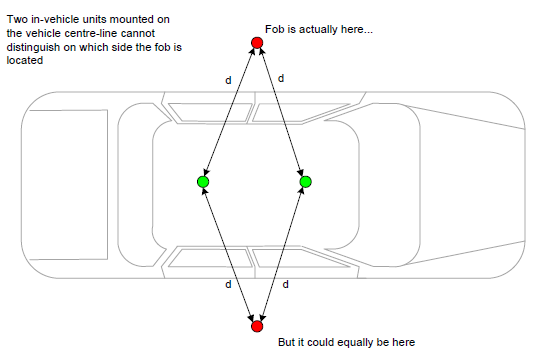
DecaWave Solution: A single two-way ranging exchange between one in-vehicle unit and a fob, while sufficient to measure how far away the fob is from the vehicle, is not sufficient to determine on which side of the vehicle the fob is located because only one piece of information – a single distance – is available.
Detecting on which side of the vehicle the fob is located
In order to determine on which side of the vehicle the fob is located, two pieces of information are required – two distances from two in-vehicle units, for example, provided of course that these in-vehicle units are positioned in an appropriate way.
Two in-vehicle units on vehicle center line
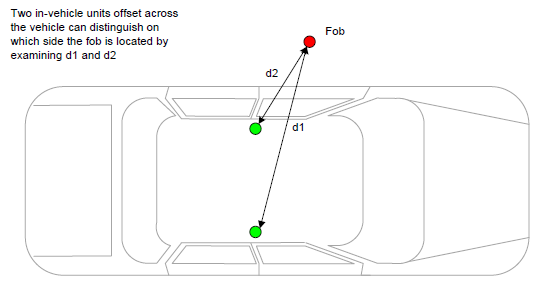
If the two units are mounted across the vehicle as shown in the figure below, then it becomes possible to uniquely identify the side of the vehicle on which the fob is located.
Two in-vehicle units mounted across the vehicle
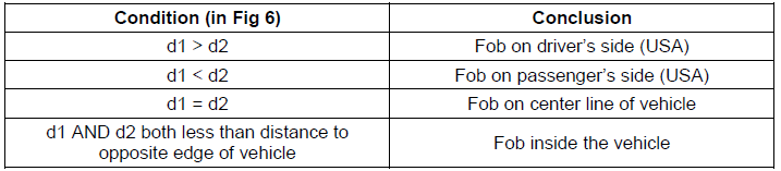
Analysis of measured distances
Problem: The question then arises, how close together can the in-vehicle units be located? If they can be mounted close enough together then it becomes possible to fabricate them as one unit for ease of installation into the vehicle. This is where the +/- 10cm distance measurement accuracy comes into play.
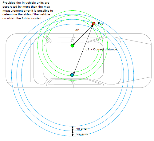
DecaWave Solution: For the two in-vehicle units to reliably determine correctly the side of the vehicle on which the fob is located the separation between the two in-vehicle units must be greater than the maximum possible error in the distance measurement. So, with +/-10cm accuracy, in the worst case, the measurement from one in-vehicle unit to the fob could be +10cm in error while the measurement from the other could be -10cm in error. To avoid drawing incorrect conclusions from the measured data, a minimum separation between the two units of 20cm is required. We can illustrate this by drawing an error boundary of +/-10cm around the distance measured from each in-vehicle unit to the fob.
Maximum measurement error determines physical separation of in-vehicle units
If the in-vehicle units are mounted closer together than the maximum measurement error, then it is not possible to reliably determine on which side of the vehicle the fob is located.
In-vehicle units separated by less than the max measurement error
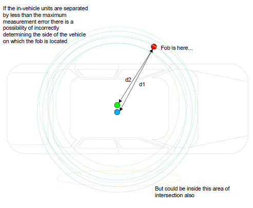
The conclusion from this analysis is that the two in-vehicle units must be separated by at least 20 cm.
Physical Implementation of the in-vehicle unit
Problem: Given that it is clear that two units are required inside the vehicle, the question then arises as to how best to implement those units.
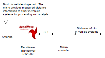
DecaWave Solutions: In its basic form a unit consists of the DecaWave transceiver, a microcontroller, and an antenna. The microcontroller controls the transceiver and implements the two way ranging exchange with the fob.
Basic Single Unit Implementation
There are 3 possibilities in terms of implementing the two units:
1. Separate antennas but only one transceiver and one microcontroller
2. Separate antennas and transceivers but only one microcontroller
3. Entirely separate units
Separate Antenna Implementation
Possible Two-Unit Implementation by switching antennas
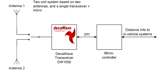
This implementation has the advantage that the comparison between the two distance measurements to the fob can be made in the microcontroller and the conclusion advised to the relevant in-vehicle systems. At first glance it would also appear that this implementation would be cheaper to implement.
The primary drawback with this system is the difficulty in switching antennas at the high frequencies involved and the inaccuracies that are introduced by the antenna connection and switching mechanisms.
Switching radio signals at the frequencies of interest (3.1 – 10.6GHz) is difficult at best and should be avoided if at all possible. The switching components are generally expensive given the frequencies at which they are operating. Switching antennas necessitates a settling period before messages can be transmitted or received since there is no guarantee that the potential at one antenna is the same as the other at switching time, so a transient may result which requires time to settle. This will limit the number of transmissions / receptions that can be made with each antenna. Without system modelling it is impossible to say what impact this might have on overall performance.
For this system to work reliably the delays introduced by the antenna connections must be known and very tightly controlled. This is difficult to do repeatedly in cable environments but is much more controllable using printed circuit board connections.
Ideally, these delays should be the same so that the same correction factor can be applied by the microcontroller to remove the “antenna delay” from the calculations (the delay between the arrival / departure of the signal at / from the antenna and the instant it is time-stamped by the receiver / transmitter. If they are not the same (i.e. unit and one antenna located on one side of the vehicle and the other antenna located on the other side of the vehicle) then different correction factors will need to be applied and these may need to be calibrated at manufacturing time to take account of cable manufacturing tolerances.
It is our view that this implementation will lead to production difficulties and an unreliable system implementation and should be avoided.
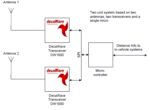
Separate Antennas and Transceivers but only one Micro-controller
This system removes the antenna switching issues with the previous implementation. It allows for the remote location of one transceiver and antenna using the SPI interface, although this range is limited because SPI was intended as an on-circuit-board serial communications interface scheme.
Because both distance measurements are calculated by one microcontroller, it is also capable of analyzing these distances and determining on which side of the car the fob is located. This information can then be provided to other in-vehicle systems. This may be a more orthogonal and “cleaner” partitioning of functionality, and may simplify other in-vehicle systems.
The fact that one microcontroller controls both transceivers means that only one can be actively communicating with a fob at any given time. In fact, this is not an issue since that is the way the system works. The fob ranges to one in-vehicle unit and then the second – it cannot range to both simultaneously.
It is our view that this is a good compromise solution, provided that the issue of communications between the microcontroller and the two transceivers via SPI is handled correctly.
Two Transceivers / Single Micro implementation
Entirely Separate Units
In-vehicle unit based on two entirely separate sub-units
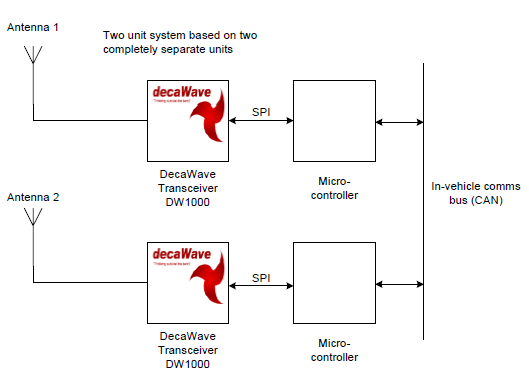
This is the obvious solution. Each microcontroller deals with its own transceiver and supplies the distance measurement data either to a processor elsewhere in the vehicle to perform the data analysis, or one of the two processors is designated as the data analysis processor and the other processor provides its measurements for analysis.
In this situation the communications between the microcontrollers could be handled over the in-vehicle communications bus (CAN, for example) or via a separate dedicated connection from one controller to the other.
The advantage of this implementation is that it allows much greater freedom in the location of the units (within the constraints of cost, manufacturability, and so on).
Other Considerations - Location of the units in the vehicle
We have already seen how the in-vehicle units must be separated by more than 20cm to take account of the maximum possible ranging error. There is another consideration to be borne in mind – that of radio propagation.
DecaWave’s technology is based on the propagation of radio waves from transmitter to receiver. The technology is exceptionally good in non-line-of sight-environments, but like all radio schemes, it will not propagate through metal plates; it can only propagate around them.
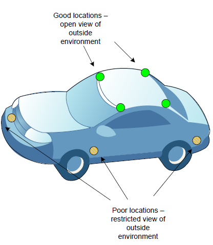
This has important implications for the location of the in-vehicle units. Positioning the units low down in the interior of the vehicle will severely restrict their “visibility” of the outside environment – behind dashboards, door panels, etc., are all poor locations for this technology.
Positioning the units high up in the headlining, the courtesy light, the sun visor mounts or other such elevated position will give a much better view of the outside environment, via the window glass, and will give better performance.
Location of in-vehicle units
Antenna Radiation Patterns
All of the discussions so far have assumed simple spherical antenna radiation patterns. These may not be the best ones to use.
For example, in the fob it may be better to use a much-less omni-directional pattern so an element of directionality is introduced and the fob must be “pointing” in the general direction of the vehicle for communications to take place.
Similarly, for the in-vehicle units, it may make sense to have oval radiation patterns rather than spherical because vehicles are generally longer than they are wide. These decisions would require further analysis.
Why DW1000 Is Ideal for Keyless Entry Systems
DecaWave’s DW1000 wireless transceiver uses Ultra Wideband radio technology. It is compliant with the IEEE 802.15.4-2011 UWB standard and is implemented using CMOS technology.
Looking at the requirements discussed above, let’s see how DecaWave’s DW1000 technology addresses them:
Interested in setting up your own RTLS scheme? Call Symmetry at (310) 536-6190, or contact us online.