- Home
- Symmetry Blog
- Magnet Magic Using The HAL 2425 Sensor From TDK Micronas & Arduino Uno
Magnet Magic Using The HAL 2425 Sensor From TDK Micronas & Arduino Uno

About Tyler Wojciechowicz
In this video, we’re using an Arduino Uno development board and a TDK-Micronas Single-axis hall effect sensor (the HAL2425). This sensor outputs an analog voltage typically between 0v-4.9v which is connected to an analog input pin on the Arduino and in-turn the analog to digital converter. When the sensor reads no magnetic field, the output is 0v; when a magnet is very close to the sensor and the magnetic field is strongest, we see 4.9v. This threshold is displayed on a series of addressable LEDs which change color (from red to green) and the number of LEDs turned on increases as magnetic field increases.
A small magnet is used after a large one and we see that it is unable to create a magnetic field strength strong enough to reach the full threshold programmed on the sensor from the same distances as the large magnet. Next, we program the HAL2425 so that the magnetic range is smaller (from 200mT to 50mT) and in turn, the small magnet is then able to reach the full threshold that the large magnet was able to.
Hopefully you are familiar with the Arduino platform and have run a few examples of your own before reaching this page. If you haven’t head on over to the office Arduino page to download the IDE:
Then head to the tutorials page to learn more about how to use your Arduino:
For this example, we are using WS2801 addressable LEDs. If you plan on using addressable LEDs as well, you will need to import a library which will allow you to do so. I’d suggest the “Adafruit WS2801 Library.” Instructions on how to import this library to your IDE are here:
Adding additional libraries to Arduino IDE
After you’ve successfully imported your WS2801 addressable LED library, download the example code:
Next, wire up your Micronas HAL2425 and LEDs:

The following should also help you with your wiring:

Diagram 1
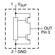
Diagram 2
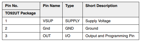
Diagram 3
Upload the code to your Arduino and hopefully your LEDs start to glow when you place a magnet near the HAL2425 sensor. If you have multiple magnets, experiment with them and notice the differences in range/threshold displayed by the addressable LEDs.
To program the settings on the HAL2425 sensor, download the programming application:
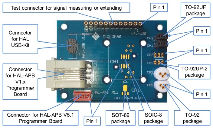
Micronas manuals, drivers, programming application and further instructions
To determine what Micronas hall sensor will work for your application, take a look at our product comparison matrix or give us a call so we can help you narrow down your choice:
Micronas sensor comparison tables
Bill of materials for this demo: Arduino Uno, HAL2425, HAL USB programmer, Micronas programer extension board, WS2801 5v LEDs, 5v power supply, magneHAL2425 Single-axis Sensor with Arduino
Applications:
- Distance, angle and linear movement
- Throttle position
- Pedal position
- EGR applications
- Contactless potentiometers
- Current sensing
Key Features:
- Ratiometric 12-bit analog output
- Versatile programming characteristics
- Low temperature drifts and programmable compensation for sensitivity and offset
- High immunity against ESD (8kV) and EMC
- Magnetic field measurements in the range up to 200mT
- Open-circuit, overvoltage and undervoltage detection
- Short-circuit protected push-pull output