- Home
- Symmetry Blog
- Part 2: Isolated Gate Drivers
Isolation Tech 101, Part 2: Isolated Gate Drivers | Symmetry Blog

About Symmetry Electronics
Established in 1998, Symmetry Electronics, a Division of Braemac, is a global distributor of electronic components and systems. Combining premier components and comprehensive value-added services with an expert in-house engineering team, Symmetry supports engineers in the design, development, and deployment of a broad range of connected technologies.
Exponential Technology Group Member
Acquired by Berkshire Hathaway company TTI, Inc. in 2017, Symmetry Electronics is a proud Exponential Technology Group (XTG) member. A collection of specialty semiconductor distributors and engineering design firms, XTG stands alongside industry leaders TTI Inc., Mouser Electronics, and Sager Electronics. Together, we provide a united global supply chain solution with the shared mission of simplifying engineering, offering affordable technologies, and assisting engineers in accelerating time to market. For more information about XTG, visit www.xponentialgroup.com.

Many considerations come into play when choosing the right isolator for your application. In a new blog series from Symmetry Electronics, we will be covering the different types of isolators available. In Part 1, we covered digital isolators. For Part 2, we will be providing an overview of isolated gate drivers, how they work, and when to use t
Keep reading to learn everything you need to know about isolated gate drivers.
Isolated Gate Drivers
In: 3V-5V pulse width modulated digital signal
Out: 15-30V digital signal
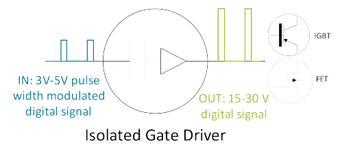
An IGBT/power MOSFET is a voltage-controlled device that is used as a switching element in power supply circuits and motor drives, amongst other systems. The gate is the electrically isolated control terminal for each device. The other terminals of a MOSFET are source and drain, and for an IGBT they are called collector and emitter.
To operate a MOSFET/IGBT, typically a voltage has to be applied to the gate that is relative to the source/emitter of the device. Dedicated drivers are used to apply voltage and provide drive current to the gate of the power device.
This article discusses what these gate drivers are, why they are required, and how their fundamental parameters, such as timing, drive strength, and isolation, are defined.
Why use a digital isolator?
The structure of an IGBT/power MOSFET is such that the gate forms a nonlinear capacitor. Charging the gate capacitor turns the power device on and allows current flow between its drain and source terminals, while discharging it turns the device off and a large voltage may then be blocked across the drain and source terminals. The minimum voltage when the gate capacitor is charged and the device can just about conduct is the threshold voltage (VTH). For operating an IGBT/power MOSFET as a switch, a voltage sufficiently larger than VTH should be applied between the gate and source/emitter terminals.
Consider a digital logic system with a microcontroller that can output a PWM signal of 0 V to 5 V on one of its I/O pins. This PWM would not be enough to fully turn on a power device used in power systems, as its overdrive voltage generally exceeds the standard CMOS/TTL logic voltage. Thus, an interface is needed between the logic/control circuitry and the high power device. This can be implemented by driving a logic level n-channel MOSFET, which, in turn, can drive a power MOSFET.
How does a digital isolator work?
Drive Strength:
The issue of providing appropriate gate voltage is addressed by using a gate driver that does the job of a level shifter. The gate capacitor though, cannot change its voltage instantaneously. Thus, a power FET or IGBT has a non-zero, finite switching interval. During switching, the device may be in high current and high voltage state, which results in power dissipation in the form of heat. Thus, transition from one state to another needs to be fast so as to minimize switching time. To achieve this, a high transient current is needed to charge and discharge the gate capacitor quickly.
A driver that can source/sink higher gate current for a longer time span produces lower switching time and, thus, lower switching power loss within the transistor it drives.
The source and sink current rating for the I/O pins of a microcontroller is typically up to tens of milliamps, whereas gate drivers can provide much higher current. In many cases, driving a larger power MOSFET/IGBT directly with a microcontroller might overheat and damage the control due to a possible current overdraw in the digital circuit. A gate driver with higher drive capability enables fast switching with rise and fall times of a few nanoseconds. This reduces the switching power loss and leads to a more efficient system. Hence, drive current is usually considered to be an important metric in selection of gate drivers.
Corresponding to the drive current rating is the drain-source on-resistance (RDS(ON)) of a gate driver. While ideally the RDS(ON) value should be zero for a MOSFET when fully on, it is generally in the range of a few ohms due to its physical structure. This takes into account the total series resistance in the current flow path from drain to source.
RDS(ON) is the true basis for maximum drive strength rating of a gate driver, as it limits the gate current that can be provided by the driver. RDS(ON) of the internal switches determines sink and source current, but external series resistors are used to reduce drive current and, thus, affect edge rates. High-side on-resistance and the external series resistor REXT form the gate resistor in the charging path, and low-side on-resistance with REXT forms the gate resistor in the discharging
RDS(ON) also directly affects power dissipation internal to the driver. For a specific drive current, the lower value of RDS(ON) allows higher REXT to be used. As power dissipation is distributed between REXT and RDS(ON), the higher value of REXT implies more power is dissipated external to the driver. Hence, to improve system efficiency and to relax any thermal regulation requirement within the driver, the lower value of RDS(ON) is preferred for the given die area and size of the IC.
Timing:
Gate driver timing parameters are essential to evaluate its performance. A common timing specification for all gate drivers is the propagation delay (tD) of the driver, which is defined as the time it takes an input edge to propagate to the output. Rising propagation delay (tDLH) may be defined as the time between the input edge rising above the input high threshold (VIH) to the output rising above 10% of its final value. Similarly, falling propagation delay (tDHL) can be stated as the time from the input edge falling below input low threshold VIL to the time output falls below 90% of its high level. The propagation delay for output transition can be different for a rising edge and a falling edge.
The edge rates (the rise and fall times of the signal) are affected by the drive current that a part can deliver, but they are also dependent on the load being driven and are not accounted for in propagation delay calculation. Another timing parameter is pulse width distortion, which is the difference between rising and falling propagation delay on the same part. Thus, pulse width distortion (PWD) = |tDLH – tDHL|.
Due to mismatch between transistors within different parts, the propagation delay on two parts will never exactly be same. This results in propagation delay skew (tSKEW), which is defined as the time difference between output transitions on two different parts when reacting to the same input in the same operating conditions. Propagation delay skew is defined as part-to-part. For parts that have more than one output channel, this specification is stated in the same way, but is noted as channel-to-channel skew. Propagation delay skew cannot usually be accounted for in the control circuit.
In a typical setup of gate drivers used with power MOSFETs in a half-bridge configuration for power supplies and motor drive applications, if both Q1 and Q2 are on at the same time, there is a chance of shoot-through due to the shorting of supply and ground terminals. This can permanently damage the switches and even the drive circuit. To avoid shoot-through, a dead-time must be inserted in the system so that the chance of both switches being on at once is greatly reduced. During the dead-time interval, gate signal to both switches is low and, thus, the switches are ideally in off state. If propagation delay skew is lower, the dead-time required is lower and control becomes more predictable. Having lower skew and lower dead-time results in smoother and more efficient system operation.
Timing characteristics are important, as they affect the speed of operation of the power switch. Understanding these parameters leads to an easier and more accurate control circuit design.
Isolation:
It is the electrical separation between various functional circuits in a system such that there is no direct conduction path available between them. This allows individual circuits to possess different ground potentials. Signal and/or power can still pass between isolated circuits using inductive, capacitive, or optical methods. For a system with gate drivers, isolation may be necessary for functional purposes and it might also be a safety requirement. In case of any fault in this system, if the damage is limited to electronic components, then safety isolation may not be necessary, but galvanic isolation is a requirement between the high power side and low voltage control circuit if there is any human involvement on the control side. It provides protection against any fault on the high voltage side as the isolation barrier blocks electrical power from reaching the user in spite of component damage or failure.
Isolation is mandated by regulatory and safety certification agencies in order to prevent shock hazard. It also protects low voltage electronics from any damage due to faults on the high power side. There are various ways to describe safety isolation, but at a fundamental level, they all relate to the voltage at which the isolation barrier breaks down. This voltage rating is generally given across lifetime of the driver, as well as for voltage transients of a specific duration and profile. These voltage levels also correspond to the physical dimensions of the driver IC and the minimum distance between pins across the isolation barrier.
Apart from safety reasons, isolation may also be essential for correct system operation. Control signals that are level shifted and referenced to the source of the high-side transistor are required. This is known as functional isolation and it can be implemented using an isolated gate driver.
Noise Immunity:
Gate drivers are used in industrial environments that inherently have a lot of noise sources. Noise can corrupt data and make a system unreliable, leading to degraded performance. Thus, gate drivers are required to have good immunity to noise to ensure data integrity. Noise immunity pertains to how well the driver rejects electromagnetic interference (EMI) or RF noise and common-mode transients.
EMI is any electrical noise or magnetic interference that disrupts the expected operation of the electronic device. EMI, which affects gate drivers, is a result of high frequency switching circuits and is mainly created due to the magnetic field from large industrial motors. EMI may be radiated or conducted and can couple into other nearby circuits. Hence, immunity to EMI or RF immunity is a metric that refers to the ability of a gate driver to reject electromagnetic interference and maintain robust operation without errors. Having high EMI immunity allows drivers to be used in close proximity to large motors without introducing any faults in data transmission.
The isolation barrier is expected to provide high voltage isolation across grounds at different potentials. But high frequency switching results in short edges for voltage transitions on the secondary side. These fast transients are coupled from one side to the other due to parasitic capacitance between the isolation boundary, which can lead to data corruption. This can be in the form of introducing jitter in the gate drive signal or inverting the signal altogether, leading to poor efficiency or even shoot-through in some cases. Thus, a defining metric for gate drivers is common-mode transient immunity (CMTI), which quantitatively describes the ability of an isolated gate driver to reject large common-mode transients between its input and output. The immunity of a driver needs to be high if the slew rates in the system are high. Thus, CMTI numbers are particularly significant when operating at high frequencies and large bus voltages.
What are ideal applications for Digital Isolators?
Industrial automation
- High noise immunity
- Reliability (high voltage lifetime)
- Signal integrity (failsafe data & low skew)
- UL, VDE/IEC certification
EV/HEV
- Low emissions
- Reliability (high voltage lifetime)
- Signal integrity (failsafe data & low skew)
- AEC-Q200 qualification
Power supply solutions
- Low latency, skew
- Protection features (overlap, UVLO etc.)
- Reliability (high voltage lifetime)
- UL, VDE/IEC certification
Inverters – solar & motor control
- Low latency, skew
- Reliability (high voltage lifetime)
- Signal integrity (failsafe data & low skew)
- UL, IEC/VDE certification
Where do I find the best Isolated Gate Drivers for my needs?
Si823x
- Drives MOSFET based systems
Si826x
- Replaces Opto-drivers
Si828x
- Drives IGBT systems
Si827x
- Newest MOSFETs
- GaN
Si8239x
- For 2.5 V VDD systems
Si875x
- SSR replacement
Silicon Labs’ products provide the best performance and reliability in the industry. With Silicon Labs' isolators, new designs receive:
- Highest noise immunity
- Fastest data rates & lowest prop delays
- Failsafe data transmission
- Lowest EMI emissions
- Highest reliability
Looking to integrate Silicon Labs products with your design? Our Applications Engineers offer free design and technical help for your latest designs. Contact us today!
About Symmetry Electronics
Established in 1998, Symmetry Electronics, a Division of Braemac, is a global distributor of electronic components and systems. Combining premier components and comprehensive value-added services with an expert in-house engineering team, Symmetry supports engineers in the design, development, and deployment of a broad range of connected technologies.
Exponential Technology Group Member
Acquired by Berkshire Hathaway company TTI, Inc. in 2017, Symmetry Electronics is a proud Exponential Technology Group (XTG) member. A collection of specialty semiconductor distributors and engineering design firms, XTG stands alongside industry leaders TTI Inc., Mouser Electronics, and Sager Electronics. Together, we provide a united global supply chain solution with the shared mission of simplifying engineering, offering affordable technologies, and assisting engineers in accelerating time to market. For more information about XTG, visit www.xponentialgroup.com.