- Home
- Symmetry Blog
- From Silicon Labs - Timing 101: The Case of the Split Termination
From Silicon Labs - Timing 101: The Case of the Split Termination

About Symmetry Electronics
Established in 1998, Symmetry Electronics, a Division of Braemac, is a global distributor of electronic components and systems. Combining premier components and comprehensive value-added services with an expert in-house engineering team, Symmetry supports engineers in the design, development, and deployment of a broad range of connected technologies.
Exponential Technology Group Member
Acquired by Berkshire Hathaway company TTI, Inc. in 2017, Symmetry Electronics is a proud Exponential Technology Group (XTG) member. A collection of specialty semiconductor distributors and engineering design firms, XTG stands alongside industry leaders TTI Inc., Mouser Electronics, and Sager Electronics. Together, we provide a united global supply chain solution with the shared mission of simplifying engineering, offering affordable technologies, and assisting engineers in accelerating time to market. For more information about XTG, visit www.xponentialgroup.com.
Welcome to another edition of the Timing 101 blog from Silicon Labs' Kevin Smith.
As I write this post it is late November. Here in the US we celebrate Thanksgiving Day on the fourth Thursday of November each year. It is customary to celebrate with friends and family and to give thanks for ones blessings in general and over the past year.
From a technical perspective, one of the things I am thankful for are the previous generations of engineers that laid the groundwork for our industry, and that trained, mentored, or otherwise gave opportunities to the current generation of engineers. Which reminds me of a particular topic...
The Split Termination
This month I would like to expand a little on a subject I first introduced in the Timing Knowledge Base article Terminating Differential Transmission Lines to Minimize CM Noise. That article described a relatively simple but very practical differential circuit termination suggested to me by an experienced EMI engineer many years ago. Think of it as a tip similar to the sort of thing found in QST’s old monthly “Hints & Kinks” column, now known as "Hints & Hacks."
I had never run across it in school and had never seen it in print but I have since used it ubiquitously. This is the case of the split termination and is the subject of this month’s column. The idea in a nutshell is expressed in the figure below. The arrow is to suggest we should generally move from the left hand “textbook” termination to the right hand more practical termination.
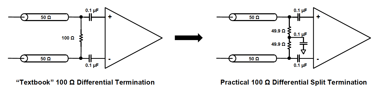
Many output clock formats such as CML, LVDS, and LVPECL are routed and terminated differentially. This is usually illustrated as a pair of single-ended nominal uncoupled 50 Ω transmission lines (one for each polarity) terminating in to an ideal 100 Ω resistor at the far end or receiver end of the circuit. This is depicted on the left hand side as the “Textbook” 100 Ω Differential Termination.
However, consider what happens when driving both input transmission lines simultaneously with the same voltage signal as can happen with noise. This is the Common Mode (CM) case as opposed to the usual Differential Mode (DM) case. Since the voltage is the same on both sides of the 100 Ω termination resistor, there is no current flow. Therefore, the CM signal doesn’t “see” the termination resistor at all and the high impedance receiver will look like an open. (The CM transmission line impedance in this example is 50 Ω // 50 Ω = 25 Ω.) So from a CM perspective we have a “noisy” signal generator driving a 25 Ω transmission line in to an open which means CM noise will be reflected, likely many times.
CM noise can arise from power supplies and crosstalk impacting both transmission lines similarly. Further, even if you don’t have a noisy board, CM noise can also arise from imbalanced transmission lines or skew which is very common, if you will pardon the pun.
How could we terminate both DM and CM? The practical split termination on the right is a T-network attempt to do this requiring only 2 more components and AC-coupled access to GND. Note that this particular termination does not increase the DC loading on the driver.
There are other approaches but these may require more components, more DC current draw, more matching, or possibly a bias voltage. (Incidentally, this differential split termination is not to be confused with LVPECL pullup and pull-down terminations which occasionally are referred to as “split” terminations also.)
The split termination explicitly splits the load termination and enforces a practical AC GND at the center-tap. Now CM current will flow and the CM signal will “see” a matching impedance, over the frequencies of interest. The 49.9 Ω selection is the closest 1% value to nominal 50 Ω. By contrast, a signal driven differentially will not “see” the center-tap capacitor to GND.
Application Details
Intuition suggests correctly that the center-tap capacitor enforces the CM voltage to see a low impedance to GND. The value 0.1 μF is a good large value and can be adjusted if necessary. There are a couple of more quantitative approaches to sizing the capacitor.
(1) Size the capacitor so as to hold the charge steady during a maximum expected Δt skew (reference).
(2) Consider the termination as a CM noise low pass filter with the corner frequency calculated as follows:
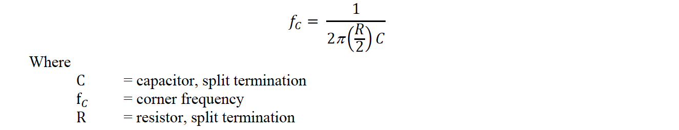
For example, if R = nominal 50 Ω and C = 0.1 μF then the corner frequency is ≈ 64 kHz which should generally be plenty low enough.
A similar version of this termination is used in CAN (Controller Area Network) applications for this purpose, supplying a special SPLIT CM voltage bias instead of GND. For an example of this, see NXP Semiconductors' AN10211, TJA104 High-Speed CAN Transceiver.
As noted in the original KB article, many SOCs and FPGAs support internal differential terminations. However, they usually do not support CM termination or give pin access to support a center-tap. (The CAN transceiver example cited above is an exception.) Therefore, if CM noise is an issue, it is best to disable the internal termination if possible, and use a higher performance external differential split termination instead.
Conclusion
This month I’ve provided a little more insight in to the differential split termination first described in a KB article. In this Thanksgiving season, I am grateful for these and other circuit tips I have received over the years.
This submission will be posted too late to beat the holiday so a belated Happy Thanksgiving to you all! I hope you have enjoyed this Timing101 article. As always, if you have topic suggestions, or there are questions you would like answered, appropriate for this blog, please send them to kevin.smith@silabs.com with the words Timing 101 in the subject line. I will give them consideration and see if I can fit them in.
Thanks for reading. Keep calm and clock on.
Source: https://www.silabs.com/community/blog.entry.html/2017/11/29/timing_101_the_case-Yf00


About Symmetry Electronics
Established in 1998, Symmetry Electronics, a Division of Braemac, is a global distributor of electronic components and systems. Combining premier components and comprehensive value-added services with an expert in-house engineering team, Symmetry supports engineers in the design, development, and deployment of a broad range of connected technologies.
Exponential Technology Group Member
Acquired by Berkshire Hathaway company TTI, Inc. in 2017, Symmetry Electronics is a proud Exponential Technology Group (XTG) member. A collection of specialty semiconductor distributors and engineering design firms, XTG stands alongside industry leaders TTI Inc., Mouser Electronics, and Sager Electronics. Together, we provide a united global supply chain solution with the shared mission of simplifying engineering, offering affordable technologies, and assisting engineers in accelerating time to market. For more information about XTG, visit www.xponentialgroup.com.