- Home
- Symmetry Blog
- From Silicon Labs: Kernel 201: UI Tasks
From Silicon Labs: Kernel 201: UI Tasks

About Symmetry Electronics
Established in 1998, Symmetry Electronics, a Division of Braemac, is a global distributor of electronic components and systems. Combining premier components and comprehensive value-added services with an expert in-house engineering team, Symmetry supports engineers in the design, development, and deployment of a broad range of connected technologies.
Exponential Technology Group Member
Acquired by Berkshire Hathaway company TTI, Inc. in 2017, Symmetry Electronics is a proud Exponential Technology Group (XTG) member. A collection of specialty semiconductor distributors and engineering design firms, XTG stands alongside industry leaders TTI Inc., Mouser Electronics, and Sager Electronics. Together, we provide a united global supply chain solution with the shared mission of simplifying engineering, offering affordable technologies, and assisting engineers in accelerating time to market. For more information about XTG, visit www.xponentialgroup.com.
This blog is part of the Kernel 201: Designing a Dynamic Multiprotocol Application with Micrium OS. The table of contents for this blog series can be found here.
Note: It is recommended to download the Kernel 201 application and have the code in front of you as you go through this blog post. The code can be downloaded on the Kernel 201: Project Resources page.
Introduction
Up until this point, all of the tasks covered in this blog series have been for wireless communication and the system watchdog. This post will cover the two user interface tasks: LEDs and buttons. These tasks are simple interfaces that take advantage of some of the hardware on the Thunderboard Sense 2. In a real-world application, these tasks would be just part of a number of application tasks that may interact with other sensors, user input or even other processors.
LED Task
When the LED Task is first created, there are two sets of LEDs that are initialized. The Thunderboard Sense 2 provides a simple red and green LED controlled by GPIO pins, but it also has RGB LEDs on both sides of the board. The RGB LEDs require the use of a hardware timer to control the color, so they can show any color you wish. To keep the lab simpler, the LEDs only offer red, green and yellow since those colors are available on both the GPIO LED and the RGB LEDs.
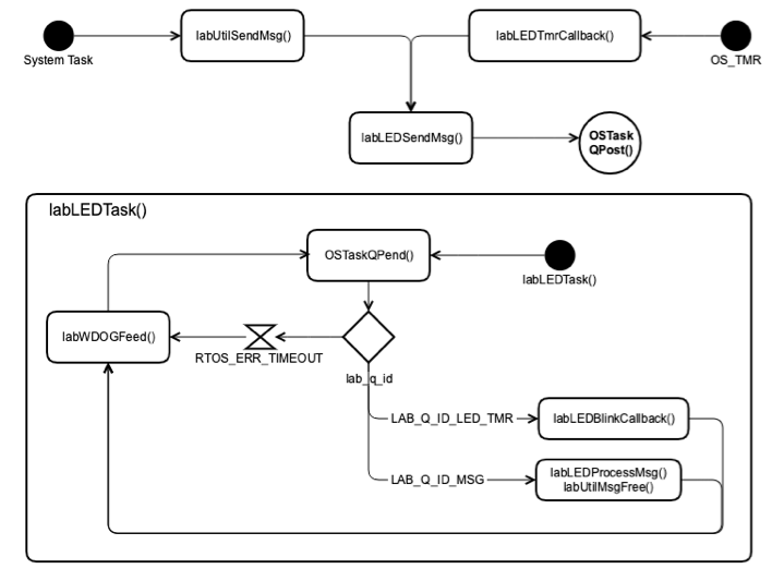
The LED Task is structured like all other tasks in the system (except for the watchdog task) in that it pends on a task message queue to perform an action.
The Task Message Queue processes two events and one RTOS error. These events are:
- RTOS_ERR_TIMEOUT
- LAB_Q_ID_MSG
- LAB_Q_ID_LED_TMR
RTOS_ERR_TIMEOUT
As part of the software watchdog, the LED Task must feed the software watchdog at a specified rate. There is a define in lab.h that all tasks use called LAB_WDOG_TASK_TIMEOUT_MS. This define specifies how often every task should check-in with the software watchdog. If the Task Message Queue does not receive a message before the timeout value is hit, the pend call returns with RTOS_ERR_TIMEOUT. Since it’s a timeout the LED Task knows that no message was received, it only feeds the software watchdog and then starts pending on the Task Message Queue again.
LAB_Q_ID_MSG
When another task in the system wishes to send a command to the LED Task, a lab message must be sent to the LED Task via the Task Message Queue. In most cases, this is either the Bluetooth or Proprietary Wireless task relaying LED control messages.
After a valid command message is successfully processed, an update is sent to both the Bluetooth and Proprietary Wireless tasks to alert them that the LEDs have been changed. The Bluetooth Web App will immediately reflect these changes due to the use of Bluetooth notifications. The Kernel 201 Instructor Application will be delayed on updating the LED status due to the Proprietary Wireless task transmitting on a fixed interval.
LAB_Q_ID_LED_TMR
When the LED Task is sent a command to blink the LED, a software timer is enabled. When the Micrium OS Software Timer expires, a callback function is executed similar to how an interrupt may trigger an interrupt routine. The software timer callback is treated similar to an interrupt function in that the code must be short because the callback function is executing out of the software timer’s callstack. Rather than controlling the LEDs from the callback, a message is sent to the LED Task via the Task Message Queue sending the message LAB_Q_ID_LED_TMR to signal that a software timer timeout occurred. The LED Task then knows based on the signal from the timer callback that it should blink the LEDs.
Button Task
After the Button Task is created, it initializes the two push buttons on the Thunderboard Sense 2. The Button Task is structured like all other tasks in the system (except for the watchdog task) in that it pends on a task message queue to perform an action. The button state is obtained by polling the GPIO state for each button’s GPIO. In low-power systems, interrupt-based buttons would make more sense but in the Kernel 201 Application, it is assumed the board is always powered via USB so low-power is not a concern.
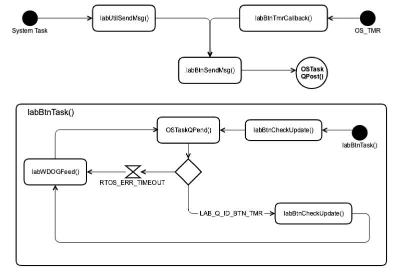
The Button Task’s Task Message Queue processes only one event and one error. If there was a desire to add the ability to change the polling rate of the buttons, the Task Message Queue could be adjusted to accept a lab message to change the polling rate.
- RTOS_ERR_TIMEOUT
- LAB_Q_ID_BTN_TMR
RTOS_ERR_TIMEOUT
As part of the software watchdog, the Button Task must feed the software watchdog at a specified rate. There is a define in lab.h that all tasks use called LAB_WDOG_TASK_TIMEOUT_MS. This define specifies how often every task should check-in with the software watchdog. If the Task Message Queue does not receive a message before the timeout value is hit, the pend call returns with RTOS_ERR_TIMEOUT. Since it’s a timeout the Button Task knows that no message was received, it only feeds the software watchdog and then starts pending on the Task Message Queue again.
LAB_Q_ID_BTN_TMR
The Button Task operates by polling the GPIO state for the buttons. The task uses a Micrium OS Software Timer similar to the LED Task. When the timer expires, a callback is executed from the software timer’s call stack. The callback function quickly checks the state of the buttons. The callback function then sends the state of the buttons to the Button Task via the Task Message Queue specifying the button state in the void* parameter.
The Button Task passes the data it receives from the time callback to the function labBtnCheckUpdate(). This function determines if either button state has changed. If one or both buttons have had a state change, the information is sent via the Task Message Queue to both the Bluetooth and Proprietary Wireless tasks. In the Bluetooth Web App the change will be seen immediately due to the use of the Bluetooth notifications. The Kernel 201 Instructor Application will not see the change immediately due to the Proprietary Wireless Task transmitting on a fixed interval. This means if you wish to see a “pushed” state for either button in the Kernel 201 Instructor Application you must hold the button until after the Proprietary Wireless task has transmitted.
Final Thoughts
The LED and Button Tasks are two very simple UI tasks implemented in the Kernel 201 Application. In a real-world application, other more complex tasks that communicate with external sensors/hardware would most likely exist alongside simple tasks such as these. These two tasks provide a solid framework to build a more complex application on top of.
Source: https://www.silabs.com/community/blog.entry.html/2019/07/16/kernel_201_ui_tasks-wcxe
Looking to integrate Silicon Labs products with your design? Our Applications Engineers offer free design and technical help for your latest designs. Contact us today!
About Symmetry Electronics
Established in 1998, Symmetry Electronics, a Division of Braemac, is a global distributor of electronic components and systems. Combining premier components and comprehensive value-added services with an expert in-house engineering team, Symmetry supports engineers in the design, development, and deployment of a broad range of connected technologies.
Exponential Technology Group Member
Acquired by Berkshire Hathaway company TTI, Inc. in 2017, Symmetry Electronics is a proud Exponential Technology Group (XTG) member. A collection of specialty semiconductor distributors and engineering design firms, XTG stands alongside industry leaders TTI Inc., Mouser Electronics, and Sager Electronics. Together, we provide a united global supply chain solution with the shared mission of simplifying engineering, offering affordable technologies, and assisting engineers in accelerating time to market. For more information about XTG, visit www.xponentialgroup.com.